Device Application
Thermostat CH-202 - is a device designed to control air conditioners by sending them IR commands. The thermostat can send commands to turn on, turn off, select the desired temperature, and select the operating modes. Before using the CH-202, you must first teach it the commands of your air conditioner. The unit has a simple algorithm for teaching IR commands. The CH-202 can expand its functionality by connecting various ConnectHome sensors.
Technical Specifications
The technical specifications of the device are shown in Table 1.
| Nominal supply voltage | 110 — 250 V AC 50/60Hz |
| Operating temperature | -40 °C to 100 °C |
| Radio signal strength | 2 mW |
| Radio frequency | 868,4 MHz EU; |
| Indoor range | up to 45m |
| Operating radius in open space | up to 75m |
| Power consumption | 0,72Вт |
| Module dimensions | 18*48*37 мм |
| Degree of protection CH-202 | IP-30 |
Connecting the device
Observe the safety rules during installation/dismantling of the device for Ukraine "DNAP 0.00-1.32-01". Before starting the installation, it is necessary to de-energize the electric network, and the protection against accidental energizing of the network must be provided. All electrical installation work must be carried out by a qualified electrician in accordance with the regulations in force. If problems arise or if the installer cannot ensure safe operation during the installation, immediately de-energize the unit and the equipment connected to it.
Teaching IR commands to the module
Before installing the module, go through the procedure of teaching IR commands. The module has a USB connector for connection to a PC and a specially designed program with which the teach-in procedure is carried out.
Preparation for the training procedure.
Download and install the program - IR - Configurator
Download and install the driver for IR - Configurator IR-Configurator
In case the program does not start, download and install an additional driver. Optional Driver.
Connect the thermostat to the PC with the USB-microUSB data cable (cord not included).
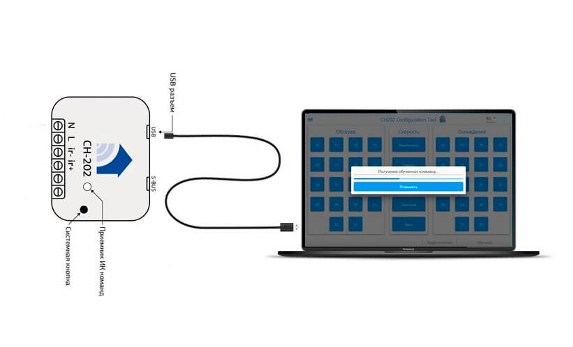
Wait for the program to connect to the device.
After connecting the device, you can start the procedure of teaching the air conditioner commands Figure 2.
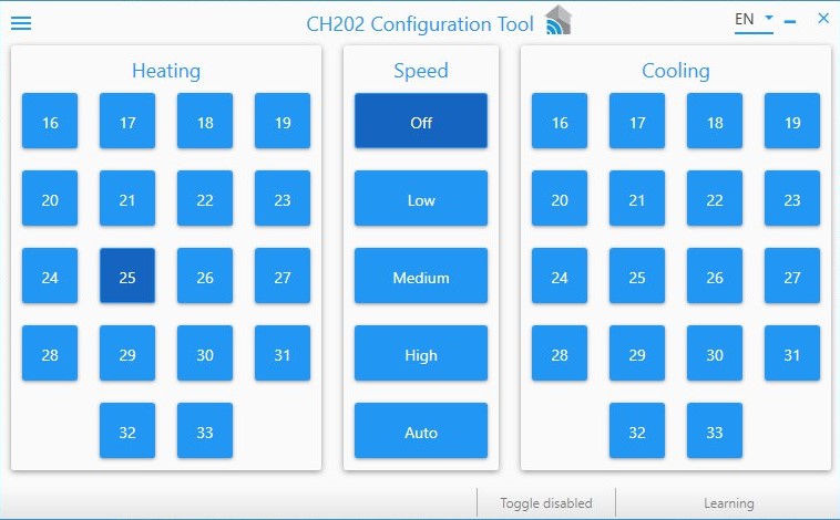
Figure 2
Before you start the training procedure, you must determine what type of commands the conditioner being trained uses. To do this:
- Turn on the air conditioner with the remote control;
- Close the remote control so that commands from it do not reach the air conditioner and press the on/off button;
- Point the remote control at the air conditioner and press the on/off button again.
If the air conditioner turns off - the air conditioner uses the toogle type command, if not (the signal will reach, but the air conditioner will remain on) - the air conditioner uses the On/Off type command.
Air conditioners that use the Toogle command do not have an "off" or "on" command. The Toogle command toggles the air conditioner to the opposite state. This means that if the air conditioner is on, it will send an "off" command, if it is off, it will send an "on" command, to the last set value.
There are 2 sets of commands for these air conditioners:
- To set the temperature and the Togle command (in one package).
- To set the temperature.
Because of this, commands are taught twice with and without the Togle command.
Training Procedure.
Once you have selected the type of commands for the air conditioner, you must teach the thermostat the three command blocks (Heating mode, Cooling mode and Speed). It is necessary to take into account the peculiarities of command transmission of some air conditioner manufacturers. Sometimes the fan speed is transmitted together with the selected mode and temperature, in this case you can not control the fan speed correctly. In this case, do not teach the fan speed unit.
The top of the CH-202 has an IR receiver window. To learn commands, point the IR transmitter on the remote control of the air conditioner toward the IR receiver. The distance between the IR receiver and the IR transmitter should not exceed three centimeters.
Mode - teaching (command type on/off)
- Go to the program menu by clicking on the button in the form of three stripes at the top right and select "Learning" mode Figure 3.
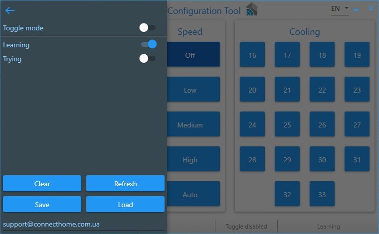
Figure 3
The current mode of the program is displayed on the bottom panel of the program Figure 4.
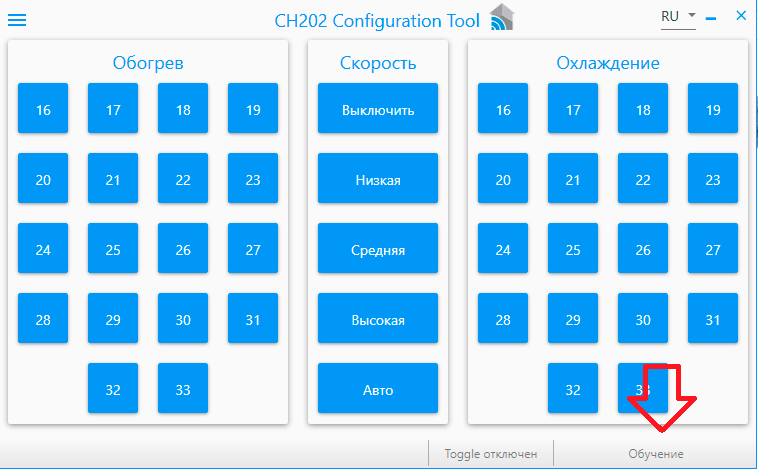
Figure 4
- Select the button you want to teach. The button will start blinking - indicating that the device is ready to start teaching.
- Prepare the air conditioner remote control to send a command (select the appropriate mode (heating/cooling), the desired temperature, etc.).
- Send the selected command using the enable button on the remote control to the IR command receiver window (hole on top of the unit).
- The button for which the command was recorded will blink green if the recording was successful, and red if unsuccessful. In case of an error, it is necessary to overwrite the command.
- Repeat the teach procedure for the remaining buttons.
Mode - learning (command type TOOGLE).
For air conditioners that use the Toogle command, be sure to teach the unit two modes of operation: commands without Toogle, commands with Toogle.
- Go to the program menu and select "Learning" and select Toogle mode Figure 5.
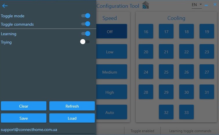
Figure 5
The current mode of the program is displayed on the bottom panel of the program Figure 6.
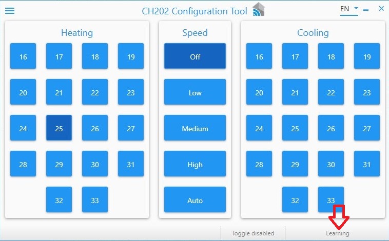
Figure 6
- Select the button you want to teach. The button will start blinking, indicating that you can start teaching.
- Prepare the air conditioner remote control to send a command (select the appropriate mode (heating/cooling), the desired temperature, etc.).
- Send the selected command to the IR command receiver window (hole on top of the device);
- The button for which the command was recorded will blink green if the recording was successful, and red if unsuccessful. In case of an error, it is necessary to overwrite the command.
- Repeat the teach procedure for the remaining buttons.
- Repeat procedure 2 - 6 for the "commands from Toogle" mode CH-202 Figure 7.
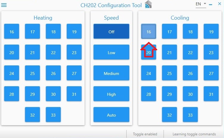
Figure 7
The current mode of the program is displayed on the bottom panel of the program Figure 8.
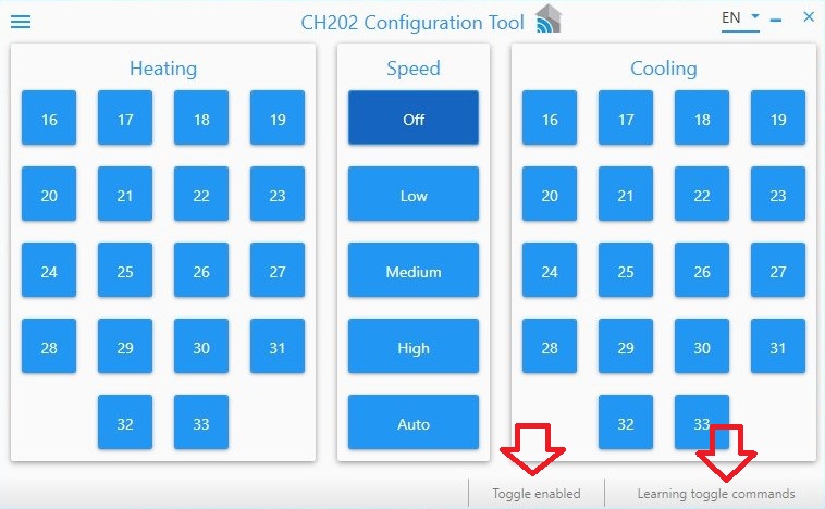
Figure 8
Mode - checks
- You can check the correctness of a taught-in command by using the "Check" mode for On/Off commands. To check a Toogle command, select the modes "Check commands without Toogle" or "Check commands with Toogle";
- Point the IR transmitter in the direction of the air conditioner and select the already taught command.
- The device will send a command to your air conditioner via the IR transmitter. If the program shows an "Error" message, you must overwrite the command for that button.
When the teach-in procedure is complete, disconnect the module from the computer and go to the next step.
Connecting to the network
To start with the device on the network, set the controller to add mode as shown in your controller's manual Figure 9.
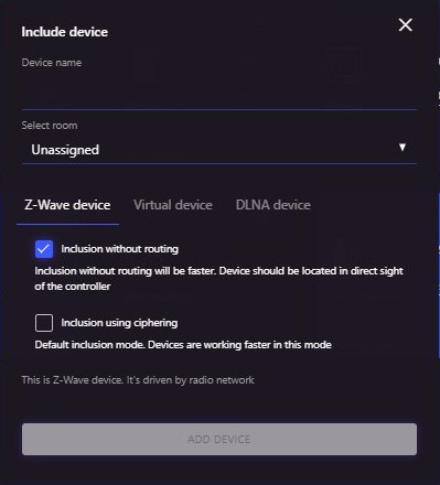
Figure 9
Then press the system button three times to start adding Figure 10.
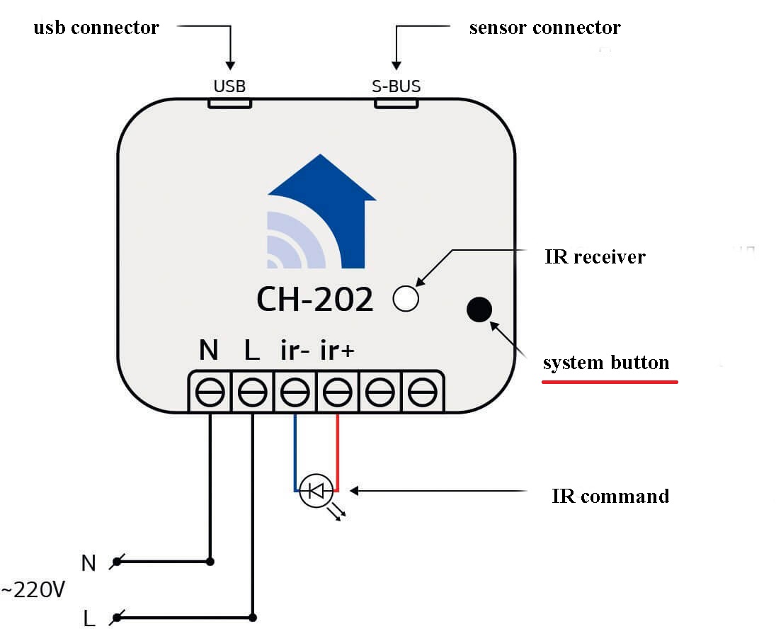
Figure 10
Then configure the link groups and parameters to your liking according to the "Links and Parameters" item.
To remove a device, put the controller into the uninstall mode and press the system button three times. Please note, once the device is removed from the network, all the settings you made will be reset to factory defaults.
Wiring diagram of the IR thermostat Figure 11.
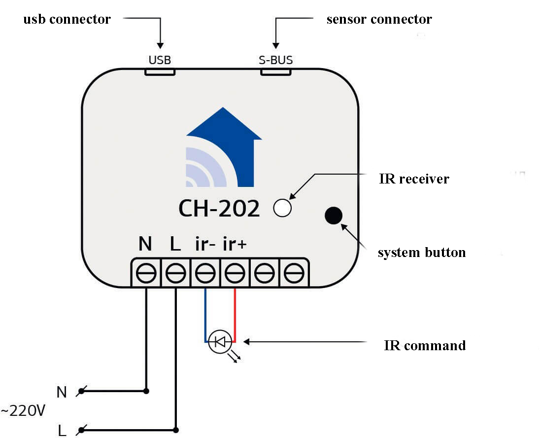
Figure 11
Where:
- L - Phase
- N - Neutral wire
- ir- is the connector for the IR transmitter (Blue);
- ir+ - connector for the IR transmitter (Red);
- metr - power sensor connection socket (only for CH-202p).
Consider the fact that the module generates a small amount of heat during normal operation. Take measures to ensure normal heat dissipation. Do not install more than one module together in a confined space, and do not allow the module to be enclosed in insulating materials.
You can place the thermostat anywhere you like, but there are a few criteria to consider:
- The IR transmitter must be fixed so that it is aimed at the IR receiver of the air conditioner;
- if the unit is CH-202p (with power sensor), one of the power wires of the air conditioner (L or N) must be passed through the sensor clip.
Connecting ConnectHome sensors
The CH-202P infrared thermostat is equipped with a CH-S06L power measurement sensor, it is connected to the terminal on the front panel of the device according to the diagram (Figure 11).
The IR thermostat also has the possibility to connect one of the different ConnectHome sensors to the S-Bus connector (Figure 1). There are two types of sensors: binary (e.g. motion sensor, which has only two values: motion/no motion) and multi-level (e.g. temperature sensor). Sensors are not included in the kit, if necessary, they can be purchased separately.
List of ConnectHome sensors that can be connected to CH-202 table 2.
| Binary sensors | Multi-level sensors |
| CH-S04 motion sensor - illumination (radius 10m) | CH-S01 temperature sensor |
| CH-S02 temperature and humidity sensor |
Sensors are connected to a special S-Bus connector located on the device body, except for the CH-S06L power sensor included in the CH-202p kit.
Sensors are used to assess the environment of your home:
- temperature measurements;
- measurement of the relative humidity of the air;
- illumination level
- the presence of movement.
In the network, the sensors are displayed as structural units (endpoints) of the CH-202 module. The data are transmitted to the controlling controller by means of radio commands.
Important: Only one ConnectHome sensor can be connected to the S-Bus connector on the CH-202. The sensor must be connected before connecting the module to the network.
If you need to connect the detector after connecting the module to the network, you must first remove the device from the network and add it again after connecting the detector.
Parameters
To determine the current status of the unit, the CH-202p thermostat provides Parameters #1, #2. With these parameters, the power consumption data can change the status of the air conditioner in the network. For example, when the air conditioner is turned on, the network status of the air conditioner will change from off to on (Operating status modes: heat or cool) from the remote control.
When the controller sends a command that selects the appropriate mode (heat, cool) with the selected temperature, the thermostat will check the current status of the air conditioner and send it the appropriate command.
If the air conditioner is turned on or set by remote control, the thermostat can detect the current status of the air conditioner (on/off), but cannot detect the current mode of operation. Therefore, the controller will be aware of the status of the air conditioner, but the operating mode will remain as it was last selected.
- 0. Yes.
- 1. No (Default).
This parameter specifies the value at which the air conditioner is considered to be on. The allowable values are 1 to 5,000 W;
— 1 No (Default).
Параметр, который указывает какой тип команд использует кондиционер.
— 1 toogle команды;
— 2 не toogle команды (По умолчанию).
Необходимо учитывать, повторное выключение будет работать только с приложения.
Sensor operating parameters
The IR thermostat is equipped with an energy measurement sensor. It is also possible to connect one of the five different ConnectHome sensors to the CH-202 module via a special S-Bus connector. In the network the sensors are displayed as endpoints of the CH-202 module. The sensor that has the lowest serial number in the network is called sensor #1, the sensor that has the highest serial number in the network is called sensor #2.
Information about binary sensors will be sent to the controller immediately, regardless of the time and number of events. For multilevel sensors, you must select the value of how much the sensor readings must change in order to send data to the controller, and you can also select the interval for forcing the sensor data to be sent.
WARNING Sending data too frequently will overload your network, which can cause devices to malfunction.
When selecting a value in the parameters, you must take into account the type of sensor to be connected.
Таблица 3.
| СН-S01 — temperature sensor. | -40 to +85C |
| СН-S02 — temperature and humidity sensor | -40 to +85C ; 0 to 100% |
| СН-S03 — ambient light sensor | 1 to 4000 lux |
IMPOrTANT: Some controllers, unfortunately, do not support entering negative numbers when selecting parameters. In this case you have to use the formula (256 - | desired value | = desired value) to select a negative value. Example - the desired value for -10 is 246 (256 - 10 = 246).
Parameters for sensor #1
This parameter is used to adjust the frequency of sending data of the sensors connected to the module.Acceptable value (1-3500):
default value depending on the type of connected sensor (temperature - 1, humidity - 5, illumination - 100, power - 50).
Allowable value (10-600 sec):
0 - do not send the sensor values forcibly;
300 seconds (Default).
The parameter works if sensor #1 is a temperature sensor, otherwise the parameter is ignored. In some cases of temperature sensor location, the measured values need to be corrected.
0.Send the actual temperature (further t) (Default);
1. t +1°С;
2. t +2°С;
3. t +3°С;
4. t +4°С;
5. t +5°С;
6. t -1°С;
7. t -2°С;
8. t -3°С;
9. t -4°С;
10. t -5°С.
Parameters for sensor #2
This parameter is used to adjust the frequency of sending data of the sensors connected to the module.Acceptable value (1-3500):
default value depending on the type of connected sensor (temperature - 1, humidity - 5, illumination - 100, power - 50).
Allowable value (10-600 sec):
0 - do not send the sensor values forcibly;
300 seconds (Default).
The parameter works if sensor #2 is a temperature sensor, otherwise the parameter is ignored. In some cases of temperature sensor location, the measured values must be corrected.
0.Send the actual temperature (further t) (Default);
1. t +1°С;
2. t +2°С;
3. t +3°С;
4. t +4°С;
5. t +5°С;
6. t -1°С;
7. t -2°С;
8. t -3°С;
9. t -4°С;
10. t -5°С.
Related
The devices can communicate with each other as well as exchange
data and other information, both with the central controller and directly without
of the controller. Each event can correspond to its own list
recipients, called the linkage group. Refer to the User Guide
Your controller to set up the connections.
Link groups ch-202:
- Group 1 - device (controller recommended), which will receive reports on changes in the thermostat status, data on instantaneous power consumption of the air conditioner, data from sensors connected to the device. Group size - 3 devices.
Manufacturer's warranty.
The warranty period is 1 year from the date of sale. Products that were transported, stored, assembled and operated with violations of the requirements for these products, as well as having mechanical damage - warranty replacement is not subject to the warranty.
Do not use the unit in any way other than that specified in this manual. The manufacturer shall not be liable for any warranty in case of improper use, modification or painting of the device. Immediately after opening the package, be sure to check the device for damage. If there is visible damage, do not connect or use the device.
Briefly about the C-Home system
All C-Home devices use a reliable and completely safe radio channel, on the basis of which the modules are combined with each other in a single network, which allows you to receive and transmit control signals to other devices in the network, using intermediate neighboring nodes.
The C-Home system has the ability to automatically reconstruct data transmission routes, depending on external factors, for example, if there is an obstacle between two neighboring devices, the signal will go through other nodes in the network in range.
C-Home is a two-way network. The devices can not only send control commands, but also wait for confirmation of their delivery and query the current status of the device. If the sending was not successful, the system tries to send the command another way.
The central element of the C-Home network is the Butler, which stores information about the network topology. It allows you to add and remove devices from the network and control all devices remotely. Not only C-Home company devices, but also more than 4,500 devices of various types and manufacturers can be connected to the Butler, which enables the implementation of any home automation tasks.