Product application
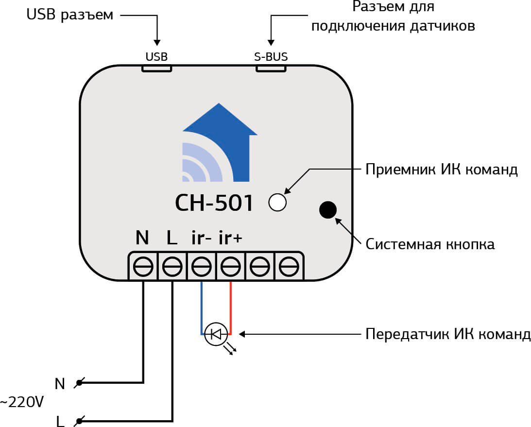
ИК-модуль СН-501 – это устройство, предназначенное для управления любым ИК прибором (телевизор, кондиционер, плеер, ресивер), посредством отправки ИК команд. ИК-модуль может отправлять любые команды, которые дублируют команды пульта управления: включение, выключение, громкость, выбор канала ТВ и т.п. Устройство имеет несложный алгоритм обучения ИК командам. Перед использованием СН-501, сперва необходимо обучить его командам Вашего ИК — устройства при помощи программы Constructor Virtual Device (Driver).
The CH-501 can expand its functionality by connecting a variety of ConnectHome sensors.
The advantages of the CH-501:
- Allows you to control an IR device from any manufacturer using IR commands;
- Simple training procedure;
- Совместим со всеми контроллерами.
Complete
- IR module CH-501 (version 1.0);
- 2. infrared transmitter;
Technical Specifications
| Nominal supply voltage | 110 — 250 V AC 50/60Hz |
| Operating temperature | -40°C to +80°C |
| Radio signal strength | 2 mW |
| Radio frequency | 868,4 MHz EU; 869,2 MHz RU; |
| Indoor range | Up to 45 m |
| Operating radius in open space | Up to 75 m |
| Power consumption | 0,72W |
| Module dimensions | 18мм*48мм*37мм |
| Degree of protection CH-202 | IP-30 |
Connecting the device
Warning! This device is powered by 220V 50Hz. Observe safety rules during installation/dismantling of the device. Before starting the installation, de-energize the electric network and provide protection against accidental energizing of the network. Electrical installation work must be carried out by a qualified electrician in accordance with current regulations. If problems arise or if the installer cannot ensure safe operation during the installation, immediately de-energize the unit and the equipment connected to it.
-
To start work, you need to connect the power supply of 220 V to the device Figure 1;
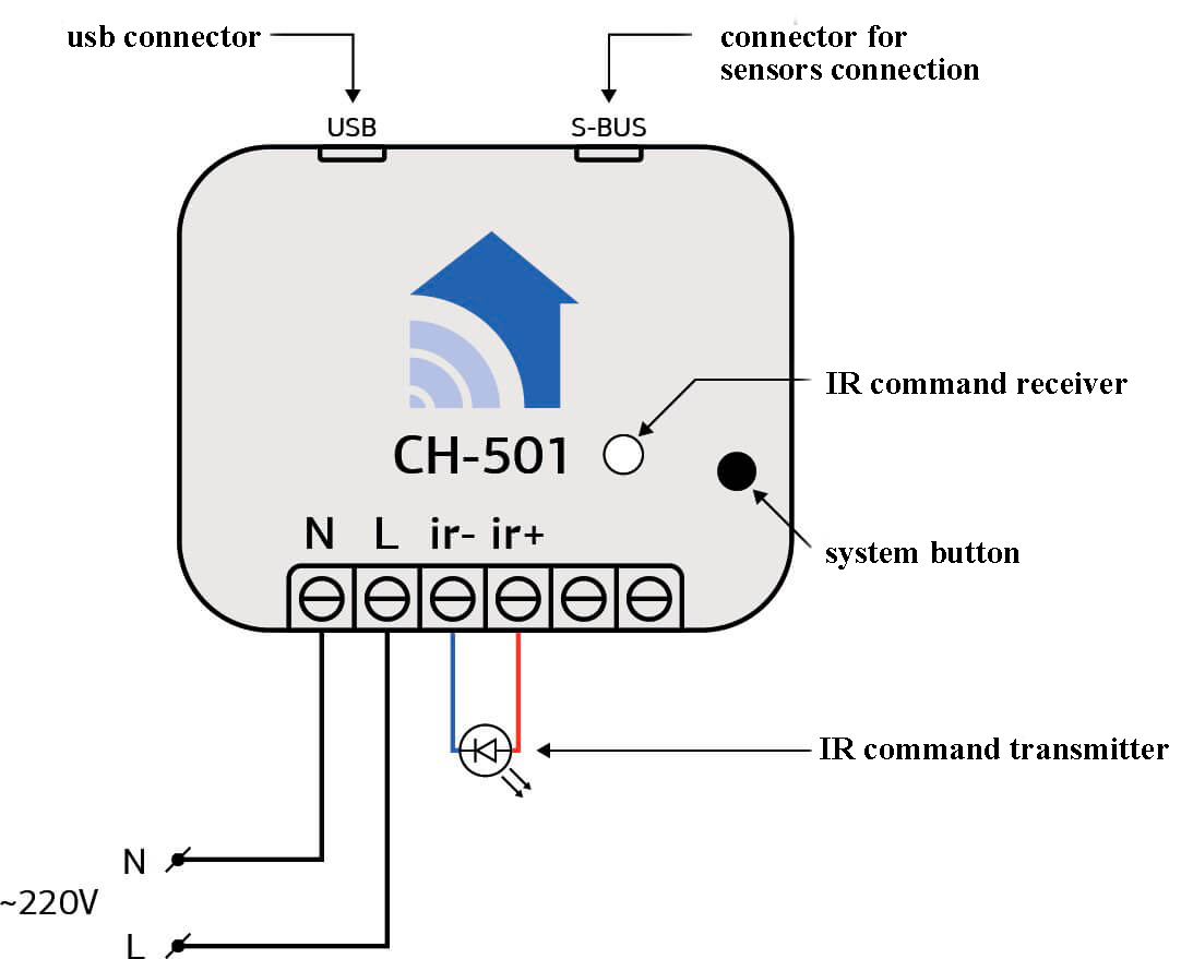
Figure 1
-
Next, you need to add the device to the controller, to do this, go to your controller tab devices and click add Figure 2.

Figure 2
Press the system key several times to put the device in add mode. After successful addition, two widgets will appear in the room you specified for the device
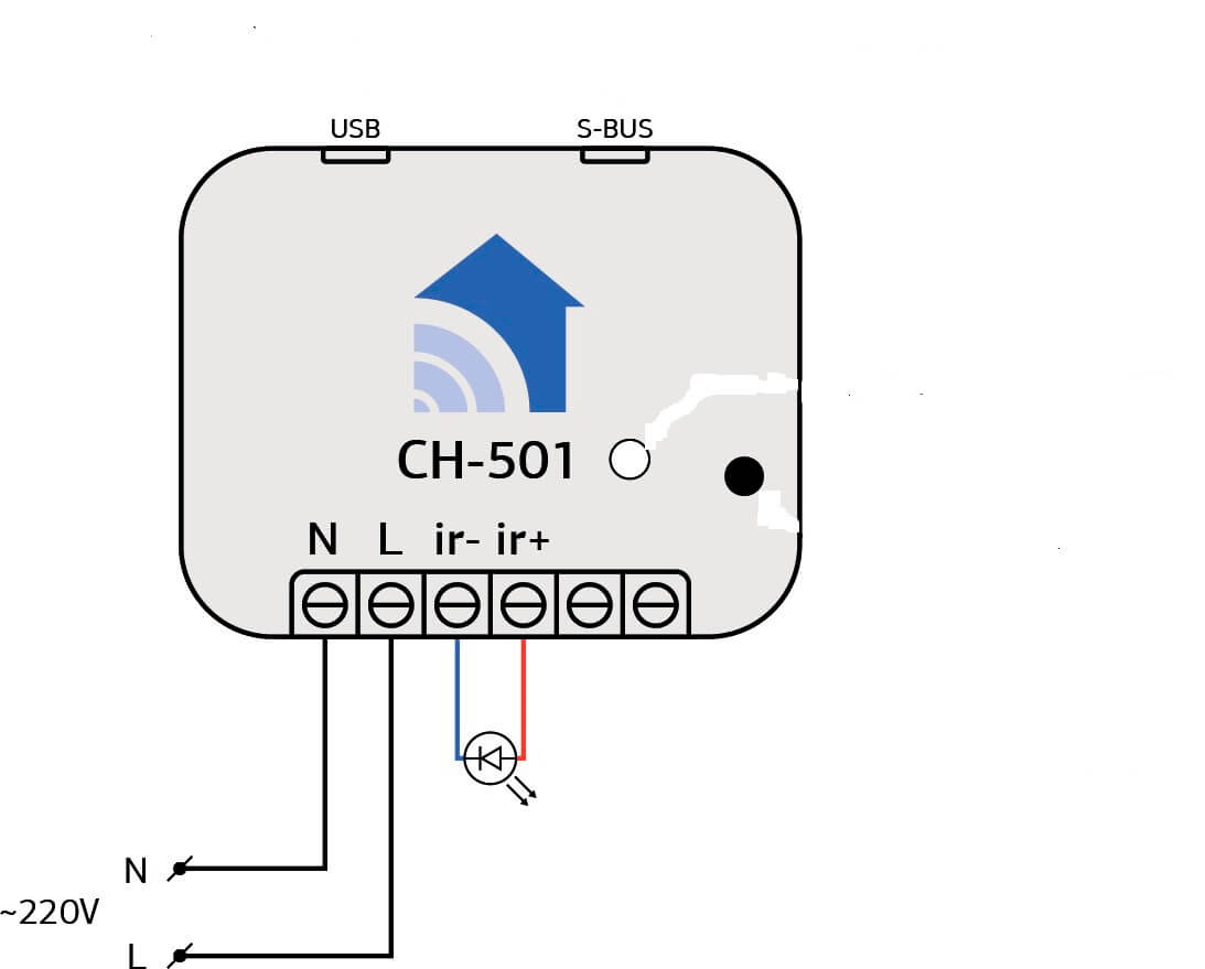
- After removing the plug from the socket 220V, connect the device to the computer with the data cable USB-microUSB, connect the IR command transmitter Figure 1.
- Нажмите по ссылке Constructor Virtual Device для скачивания программы .
- Скачайте и установите необходимый драйвер.
-
Run the downloaded Virtual Panel Consrtuctor Setup 0.1.1-b.exe
The program will be installed automatically. Make sure that the USB cable leading to the device is not accidentally touched during setup to avoid accidental disconnection. Run the program, the device will be searched.
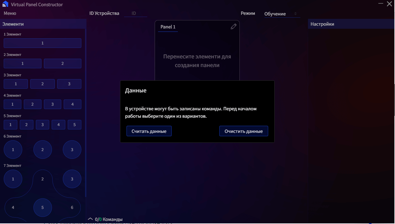
- If the search is successful, the image will appear as shown in Figure 3. If you are setting up your device for the first time or have decided to overwrite it completely, click Clear Data. If you decide to reconfigure your device, click Read Data.

Figure 3
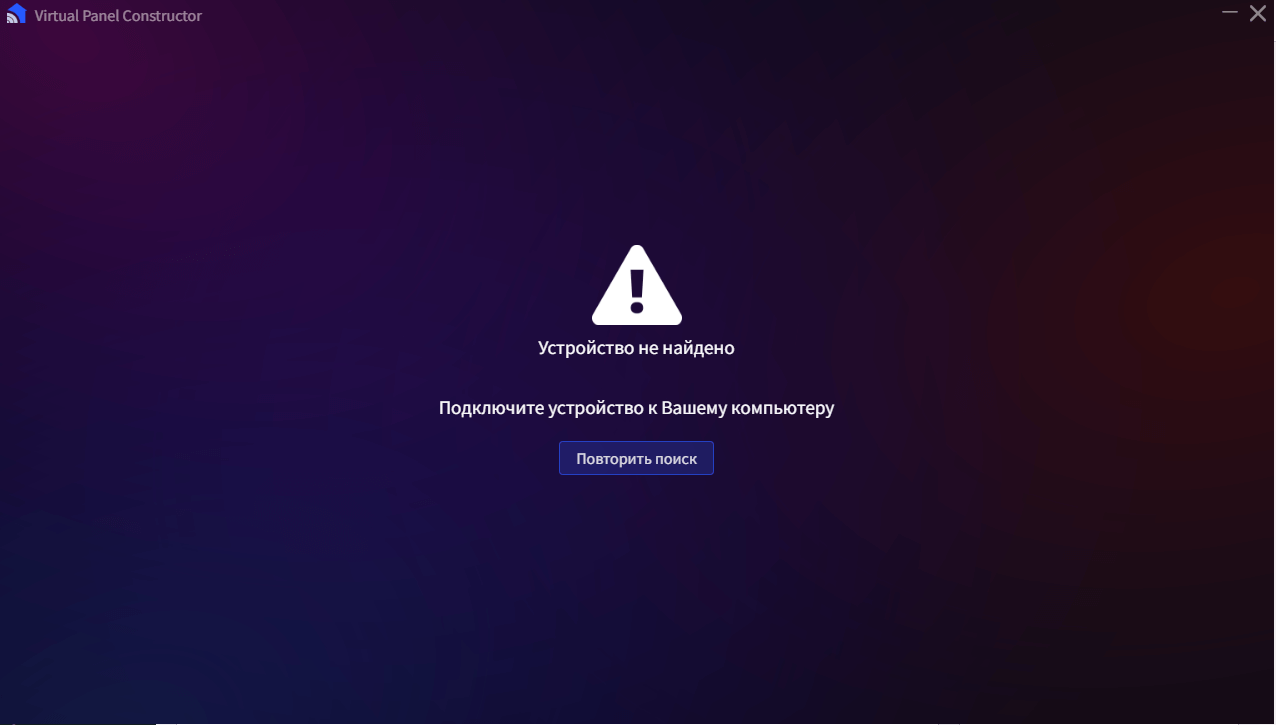
In case of an unsuccessful search Figure 4
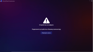
Figure 4
- Make sure that the connection is intact.
- Make sure that your USB-microUSB cable is dated.
- Register and download the official Silicon Labs driver depending on your system Driver. Unzip the driver to a separate folder, run the installer depending on the size of your system CP210xVCPInstaller_x64/x86. Repeat the device search.
- In case the above steps did not help or if the problem occurs again. Go to Device Manager Figure 7, ports, Silicon Labs, properties, driver and remove the driver. Remove the USB cable from the device and put it back, search again, in case of failure reinstall the driver manually as described above.
- If the search is successful, the image will appear as shown in Figure 3. If you are setting up your device for the first time or have decided to overwrite it completely, click Clear Data. If you decide to reconfigure your device, click Read Data.
Working with the Virtual Panel Consrtuctor
-
To configure the Virtual Panel Consrtuctor language, go to menu, languages and change it Figure 8
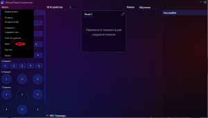
Figure 8
-
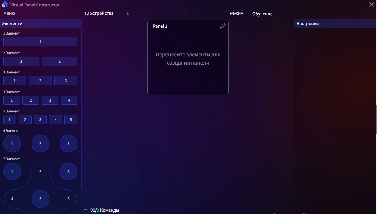
The front panel of Figure 9 contains:

Figure 9
- Elements seven types of elements to fill in their commands;
- Device ID;
- The Panel contains panels that are filled with elements to simulate a control panel;
- Modes in which an element is selected to teach a command or give a command to an element;
- Settings, in which the elements are filled with commands.
-
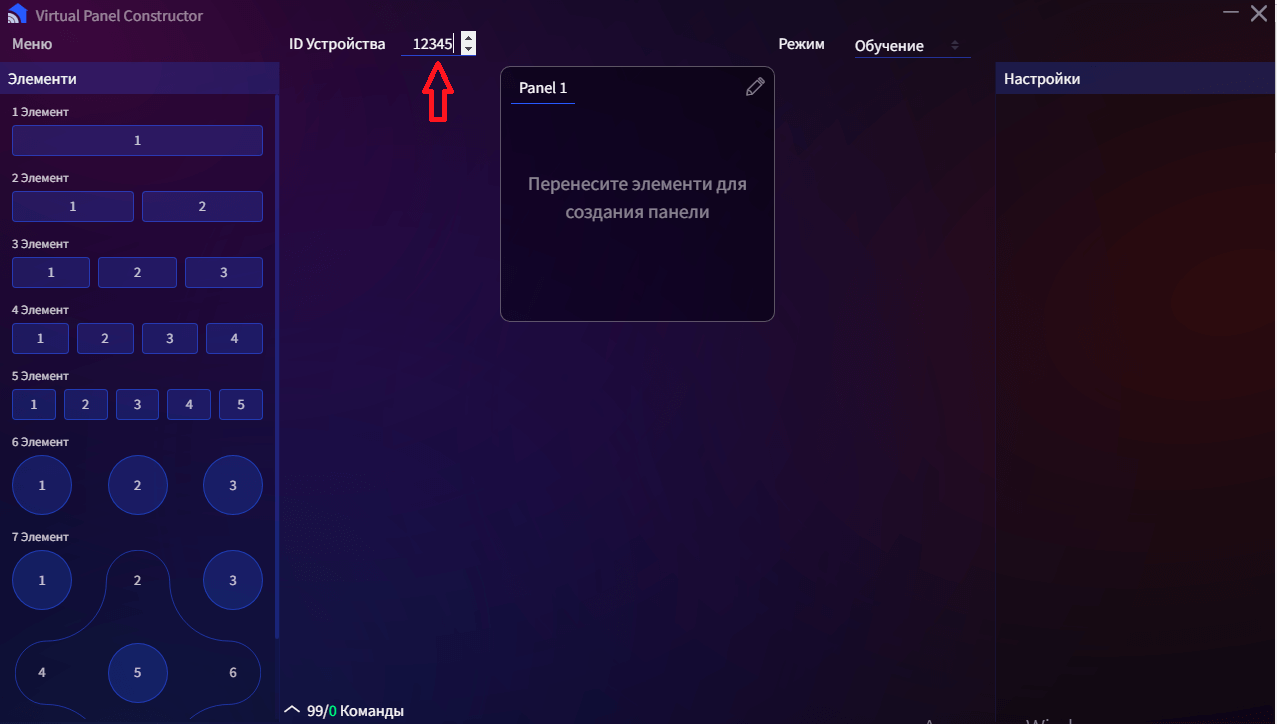
To get started, add the ID of your device from the controller (figure 10) to the appropriate field in the program
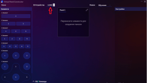
Figure 10
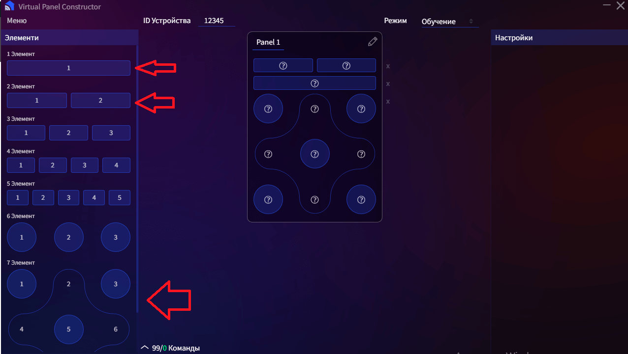
- Drag and drop items into the panel to form the panel you want Figure 11.
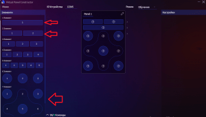
Figure 11
-
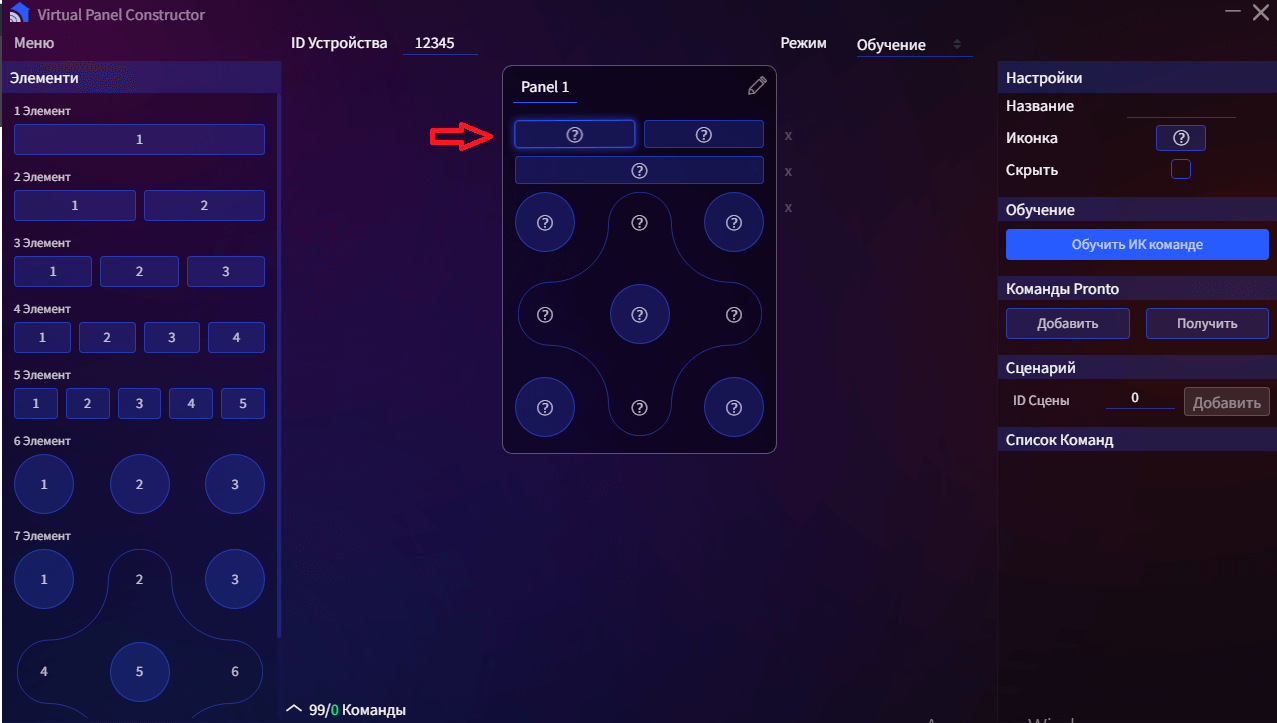
To fill an item, click on it Figure 12.
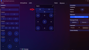
Figure 12
In the settings, enter the name of the item (hereinafter the button) or the icon with which it will be displayed. You can hide the button if you don't like its current location by checking the Hide box.
-
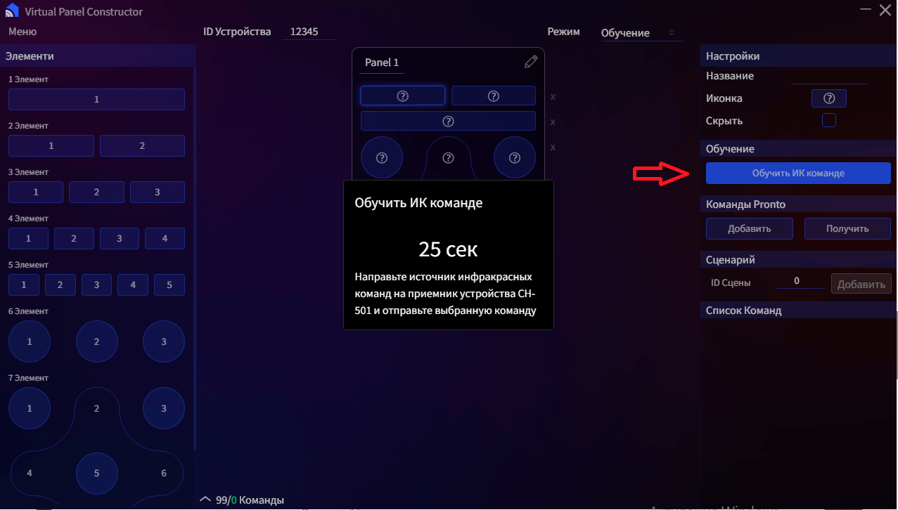
To teach the button, take the remote control from the device you need and point it at the IR command receiver figure 1, press teach IR command and the button you need from the remote control of your device. If successful, the image will appear Figure 13.
After that you can save the configuration (point 12)
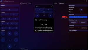
Figure 13
-
Button can be taught commands "Promto", if you have the code of the command press add, the window will appear Figure 14. Copy the code into the field and click add.
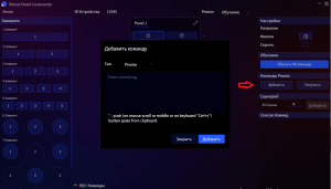
Figure 14
-
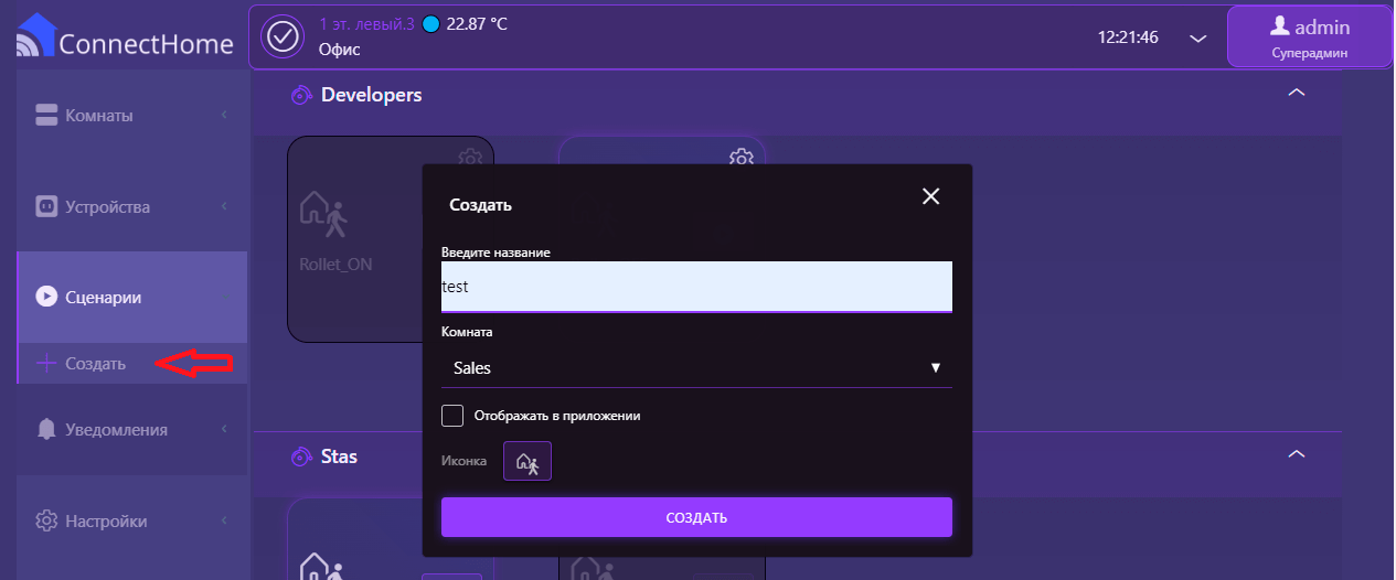
It is possible to assign the execution of the script from the controller to the button in the created console, to do this, go to the controller and hover over the script setup widget

-
At the bottom of the screen you will see a line with the ID in this example ID 19.
-
Enter the resulting ID in the scene ID field and click add.
-
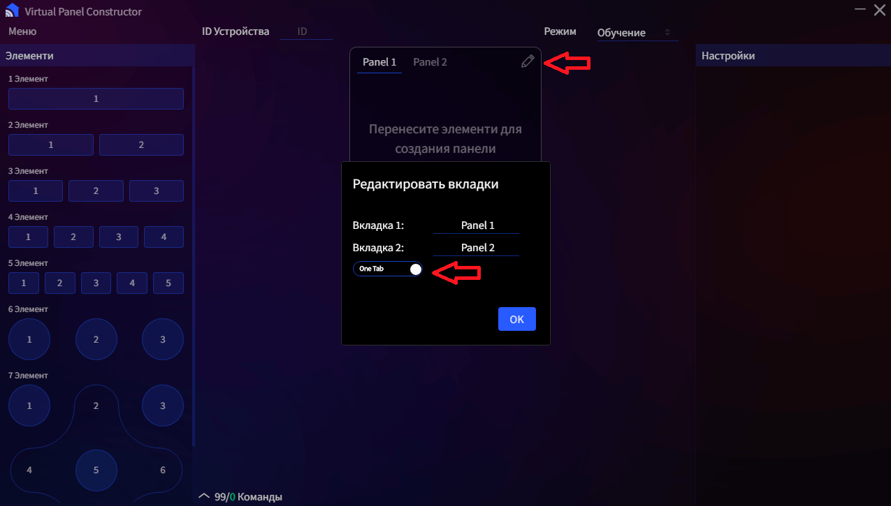
It is possible to create a second panel .
To do this, click on the image of Pencil 1 then Two Tab 2. After that, the second panel will appear.
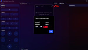
Figure 15
-
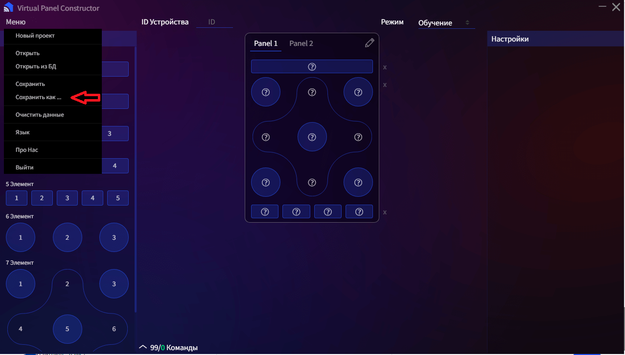
Save the configuration by pressing menu, save as, select save path, file name, save. Select the saved file and change its extension to ".json".Go to the device settings menu in the controller and load the panel Figure 16
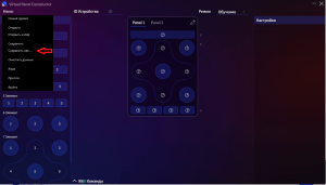
Figure 16


Connecting CONNECTHOME ConnectHome sensors.
The CH-501 IR model is a micromodule that has the ability to connect one of ConnectHome's various sensors. There are two types of sensors: binary (e.g. motion sensor, which has only two values: motion/no motion) and multi-level (e.g. temperature sensor). Sensors are not included in the kit and can be purchased separately if needed.
List of ConnectHome sensors that can be connected to the CH-501*:
| Binary sensors | Multi-level sensors |
| CH-S04.10 motion sensor - illumination (10m radius) | CH-S01 temperature sensor |
| CH-S02 temperature and humidity sensor | |
| CH-S06 power sensor |
All sensors are connected to a special S-Bus connector located on the body of the device.Sensors are used to assess the environment in your home:
- temperature measurements;
- measurement of the relative humidity of the air;
- lighting level;
- the presence of movement.
In the network, sensors are displayed as structural units (endpoints) of the CH-501 module. The data are transmitted to the controlling controller via radio commands
Important: Only one ConnectHome sensor can be connected to the special S-Bus connector on the CH-501. The sensor must be connected before connecting the module to the network.
If you need to connect a sensor after connecting the module to the network, you must first remove it and then add it again after connecting the sensor.
Choosing a place to install the IR module
You can place the CH-501 module in any convenient location, but note that the IR transmitter must be fixed so that it faces the direction of the IR receiver of the device you want to control.
Parameters
Related
Devices can communicate with each other as well as exchange data and other information both with the central controller and directly without the controller. Each event can have its own list of recipients, called a group of links. Refer to your controller's user manual to configure the links.
Manufacturer's warranty.
The warranty period is 1 year from the date of sale. Products that were transported, stored, assembled and operated with violations of the requirements for these products, as well as having mechanical damage - warranty replacement is not subject to the warranty.
Do not use the unit in any way other than that specified in this manual. The manufacturer shall not be liable for any warranty in case of improper use, modification or painting of the device. Immediately after opening the package, be sure to check the device for damage. If there is visible damage, do not connect or use the device.
Briefly about the C-Home system
All C-Home devices use a reliable and completely safe radio channel, on the basis of which the modules are combined with each other in a single network, which allows you to receive and transmit control signals to other devices in the network, using intermediate neighboring nodes.
The C-Home system has the ability to automatically reconstruct data transmission routes, depending on external factors, for example, if there is an obstacle between two neighboring devices, the signal will go through other nodes in the network in range.
C-Home is a two-way network. The devices can not only send control commands, but also wait for confirmation of their delivery and query the current status of the device. If the sending was not successful, the system tries to send the command another way.
The central element of the C-Home network is the Butler, which stores information about the network topology. It allows you to add and remove devices from the network and control all devices remotely. Not only C-Home company devices, but also more than 4,500 devices of various types and manufacturers can be connected to the Butler, which enables the implementation of any home automation tasks.