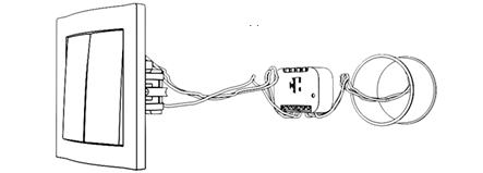
Multifunctional single-channel module СН-103 - is a device designed to control the motors of blinds, roller shutters, blinds. The actuators are controlled by means of switches or radio commands connected to the module. The device has a built-in microcontroller that allows the module to detect the position of the motor, control the position of the blinds, etc. The module is so small that it can be placed even in the installation box behind the switch (Fig. 1).
Application of the module:
- blinds actuators control
- roller shutter actuator control
- louver actuator controls
- control of awning drives and other shading systems
- control of gate drives, barriers, etc.
Technical Specifications
| Nominal supply voltage | 110 — 250 V AC 50/60 Hz |
| Maximum AC resistive load current | 8A / 230V 50/60 Hz — AC1(cos φ ≥ 0.95) |
| Maximum AC inductive load current | 8A / 230V 50/60 Hz — AC3(cos φ ≥ 0.4) |
| Maximum current of the switched DC load | 8A / 30 V — DC-1 |
| Maximum switching voltage | 230VAC/30VDC |
| Operating temperature | -10 °C to 50 °C |
| Radio signal strength | 2 mW |
| Radio frequency | 868,4 MHz EU; 869,2 MHz RU; |
| Indoor range | Up to 45 m |
| Operating radius in open space | Up to 75 m |
| Power consumption | < 0.72W |
| Module dimensions | 18*48*37 мм |
| Minimum relay life | 50,000 tap-change operations |
| Protection level | IP-30 |
Adding a module to the central controller
To add the module module into the network, put the controller into teaching mode (see the manual of your controller) and apply power to the electrical network to which the device is connected. The device will be added automatically . If this does not happen automatically, press the system button on the top cover of the unit three times briefly.
Attention! If there is a problem connecting the device to your network, you must go through the procedure of excluding it from the network and then repeat the power-on procedure.
To add removing (exclude) the module from the network, put the controller into exclusion mode (see the controller manual) and press the system button three times briefly. Please note, once the unit is excluded from the network, all the settings you made will be reset to the factory settings
You can also add/remove a device from the network with a switch which is connected to pin S1. If the switch is monostable (Parameter 15), then the addition/removal is done by triple pressing the switch for 2 seconds. If the switch is bistable (Parameter 15), the addition/removal takes place by successive combinations of switch on/off/on(1-0-1) or off/on(0-1-0) within 2 seconds.
Device control
The module can be controlled locally with a switch connected to it to contact S1 and S2. The switches can be either monostable (return or bell type) or bistable (standard switch with two fixed positions). To select the type of switch, set the corresponding value in Parameters 15 and 16.
Connecting the device
Attention! This device is powered by 230 V 50 Hz. Observe safety rules during installation/dismantling of the device. Before starting the installation, it is necessary to de-energize the electric network and the protection against accidental energizing of the network must be provided. Electrical installation work must be carried out by a qualified electrician in accordance with current regulations. If problems arise or if the installer cannot ensure safe operation during the installation, immediately de-energize the unit and the equipment connected to it.
Consider the fact that the module generates a small amount of heat during normal operation. Take measures to ensure normal heat dissipation. Do not install more than one module together in a confined space, and do not allow the module to be enclosed in insulating materials.
Electrical wiring diagram.
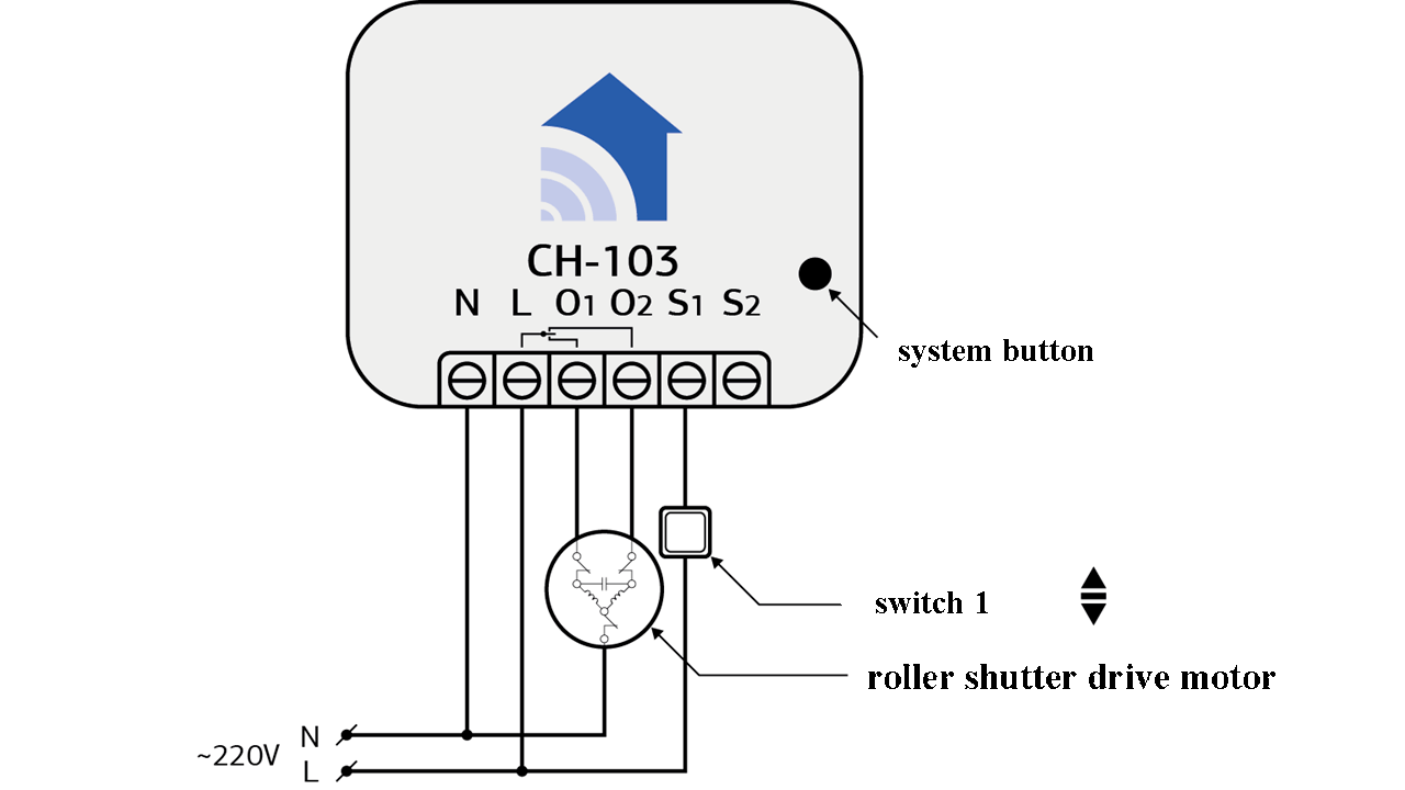
Wiring diagram of the CH-103 with one switch
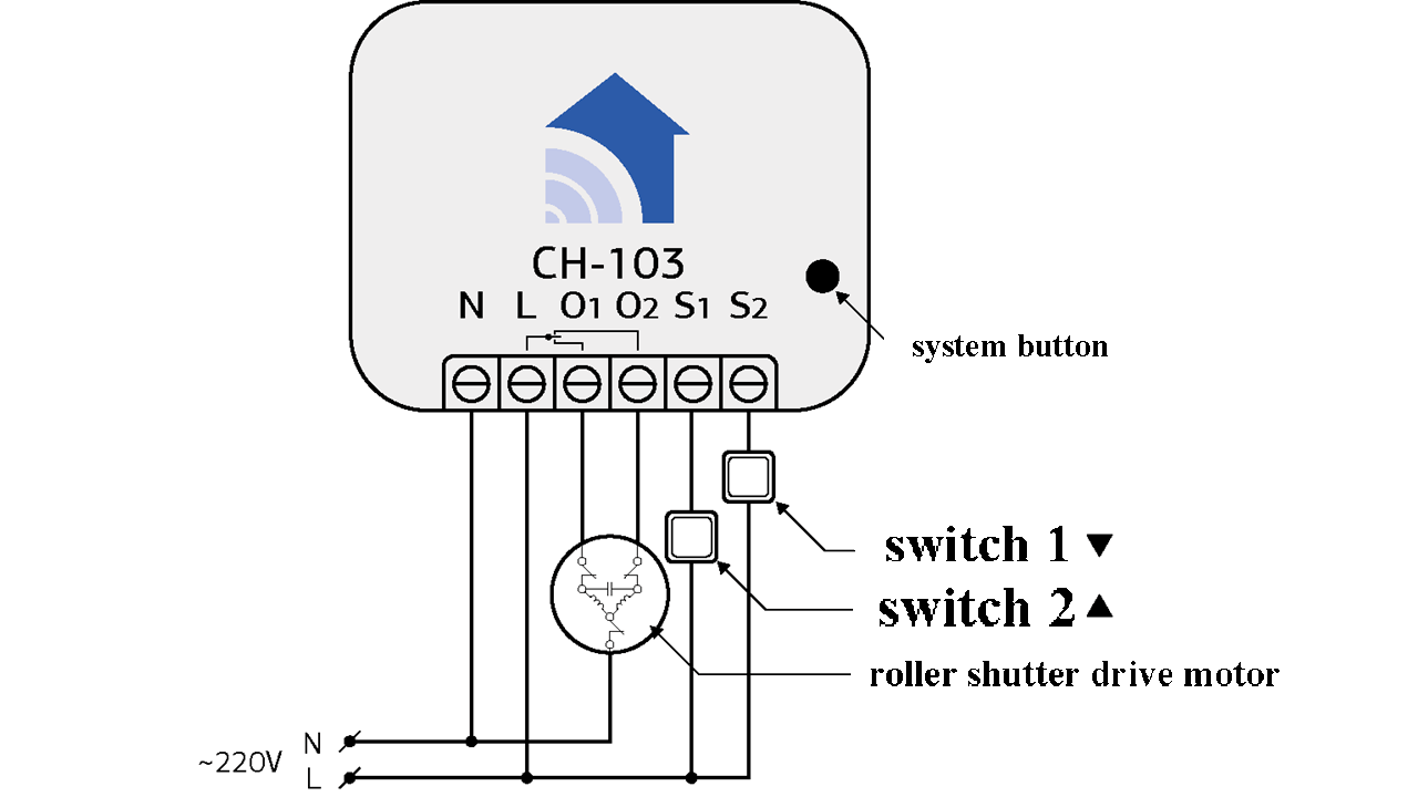
Wiring diagram of the CH-103 with two switches
Description:
- L - Phase
- N - Neutral wire
- O1 - Contact for opening
- O2 - Contact for closing
- S1 - Opening switch
- S2 - Closing switch
Parameters
CH-103 is a so-called "boxed product". This means that you just need to take it out of the box, install it according to the wiring diagram, add it to the network and the device is ready to work! But for your convenience you can fine-tune the device using a number of configuration parameters.
The CH-103 module has the ability to select the position by analyzing the full cycle time of the motor. To activate the automatic calibration, set Parameter 1 to 1 (to change the parameters, see the controller manual). The unit will start the automatic calibration. This will give the motor a command - "Open at 100%". When the internal limit switch is actuated, the motor will be given the command "Close at 100%". When the internal limit switch is actuated, the motor will be commanded again to "Open at 100%" and the calibration process will end and Parameter 1 will automatically be set to 0.
Available values:
- 0. Normal device operation (Default);
- 1. Calibration process.
WARNING!! The automatic calibration process should only be performed with the roller shutter (blinds/blinds) 100% open.
- 0. Standard motor with limit switches and position selection option (Default); For proper operation of the unit, if this value is selected, define the closing and opening times in Parameters #4 and #5, or go through the automatic calibration procedure with Parameter #1.
- 1. Motor with limit switches without position selection;
- 2. Motor controlling the louvers. When selecting this parameter, note that an additional multi-level switch will appear in the interface to control the position of the louver blades. In order for the unit to operate correctly in this mode, you must determine the time required for the full rotation of the louvers (180°), which is adjusted in Parameter #3. In addition, the device must be reconfigured or removed and reinserted into the network.
The unit of measure used in the parameter is 0.1 seconds (10 = 1 second).
The unit of measure used in the parameter is 0.1 second (10 = 1 second)
Available values are from 1 to 1000:
0 (Default).
If it is necessary to determine the time of the motor to open manually, you must change this parameter.
The unit of measure used in the parameter is 0.1 second (10 = 1 second).
Available values are from 1 to 1000:
1000 (Default).
If it is necessary to determine the closing time of the motor manually, you must change this parameter.
The unit of measure used in the parameter is 0.1 second (10 = 1 second)
Available values are from 1 to 1000:
1000(Default).
The unit of measure used in the parameter is 0.1 second (10 = 1 second)
Available values are from 1 to 1000:
0 no delay (Default).
The unit of measure used in the parameter is 0.1 second (10 = 1 second)
Available values are from 1 to 1000:
0 нет задержки (По умолчанию).
Operation parameters of pushbuttons/switches
The module has the ability to control one monostable (pushbutton, reset switch, bell switch), two monostable switches or two standard switches with two fixed positions.
To select the appropriate manual control mode, select a value in this parameter.
0. One monostable switch. In this mode, after pressing the switch, the motor will move in the opposite direction from the last movement, if you press the switch at the moment of movement, the motor will stop (the switch is connected to the contact S1, the contact S2 will not be activated).
1. Two monostable switches. A short press on a switch will send an "open/close 100%" command that corresponds to each switch. Holding down will send a command to the motor to move in the appropriate direction and releasing the switch will send a "stop" command, a short press while moving on either switch will stop the motor (Default).
2. Two standard switches (switches with two fixed positions). If one of the switches is turned on, the motor will start moving in the corresponding direction until it reaches the end position. If two switches are turned on/off at the same time, a "stop" command will be sent to the motor
Device parameters in safe mode
The CH-103 module supports transmission of radio commands in a secure mode (Security Command Class). Security Command Class is the transmission of control commands using 128-bit AES hardware encryption. This allows the device to be fully protected from unauthorized operation. Refer to your controller's manual for support of secure mode devices.
0 - Respond both to a command sent in secure mode and to an ordinary command (Default);1 - Respond only to a command sent in security mode.
0 - When you press Switch 1, send a normal command to the 2nd group of links(Default);;1 - When you press Switch 1, send a safe command to the 2nd group of links.
0 - When you press Switch 2, send the normal command to the 3rd group of links(Default);1 - When you press Switch 2, send a safe command to the 3rd group of links.
Related
Devices can communicate with each other as well as exchange data and other information both with the central controller and directly without the controller. Each event can have its own list of recipients, called a group of links. Refer to your controller's user manual to configure the links.
Thanks to the links you can synchronize the work of up to 10 modules.
OF THE CN-103 BONDING GROUPS:
- Group 1 - device (controller is recommended), which will receive reports on changes of relay state. The size of the group is 3 devices.
- Group 2 - devices, which will receive the corresponding command when you press the switch connected to the contact S1. The size of the group is 10 devices.
- Group 3 - devices, which will receive the corresponding command when you press the switch connected to the contact S2. The size of the group is 10 devices.
Manufacturer's warranty.
The warranty period is 1 year from the date of sale. Products that were transported, stored, assembled and operated with violations of the requirements for these products, as well as having mechanical damage - warranty replacement is not subject to the warranty.
Do not use the unit in any way other than that specified in this manual. The manufacturer shall not be liable for any warranty in case of improper use, modification or painting of the device. Immediately after opening the package, be sure to check the device for damage. If there is visible damage, do not connect or use the device.
Briefly about the C-Home system
All C-Home devices use a reliable and completely safe radio channel, on the basis of which the modules are combined with each other in a single network, which allows you to receive and transmit control signals to other devices in the network, using intermediate neighboring nodes.
The C-Home system has the ability to automatically reconstruct data transmission routes, depending on external factors, for example, if there is an obstacle between two neighboring devices, the signal will go through other nodes in the network in range.
C-Home is a two-way network. The devices can not only send control commands, but also wait for confirmation of their delivery and query the current status of the device. If the sending was not successful, the system tries to send the command another way.
The central element of the C-Home network is the Butler, which stores information about the network topology. It allows you to add and remove devices from the network and control all devices remotely. Not only C-Home company devices, but also more than 4,500 devices of various types and manufacturers can be connected to the Butler, which enables the implementation of any home automation tasks.