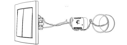
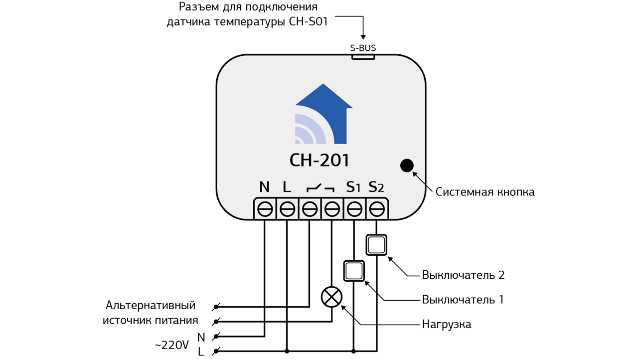
Термостат СН-201 - is a device designed to maintain a set temperature. The thermostat can control the heating element either directly (electric floor heating, electric heater, etc.) or through additional equipment (thermoelectric actuator, etc.) The thermostat can be equipped with a digital temperature sensor CH-S01, which is connected to the connector S-Bus on the thermostat. The thermostat can also use the temperature from anyone another temperature sensor of your network. The module is so small that it can even be placed in a wiring box behind a switch or socket (Figure 1).
Application of the module:
- control of the underfloor heating element
- electric heater control
- control of the electric drive of the heating system
- gas boiler control
- electric boiler control
Technical Specifications
| Nominal supply voltage | 110 — 250 V AC 50/60 Hz |
| Maximum AC resistive load current | 16A / 230V 50/60 Hz — AC1(cos φ ≥ 0.95) |
| Maximum AC inductive load current | 16A / 230V 50/60 HZ — AC3(COS Φ ≥ 0.4) |
| Maximum current of the switched DC load | 16A / 30 V — DC-1 |
| Maximum switching voltage | 230VAC/30VDC |
| Operating temperature | -10 °C to 50 °C |
| Radio signal strength | 2 mW |
| Radio frequency | 868,4 MHz EU; 869,2 MHz RU; |
| Indoor range | Up to 45 m |
| Operating radius in open space | Up to 75 m |
| Power consumption | < 0.72W |
| Module dimensions | 18*48*37 мм |
| Minimum relay life | 50,000 tap-change operations |
| Protection level | IP-30 |
| Possibility to connect S-Bus sensors | CH-S01 only |
Adding a module to the central controller
To add the module module into the network, put the controller into teaching mode (see the manual of your controller) and apply power to the electrical network to which the device is connected. The device will be added automatically . If this does not happen automatically, press the system button on the top cover of the unit three times briefly.
Attention! If there is a problem connecting the device to your network, you must go through the procedure of excluding it from the network and then repeat the power-on procedure.
To add removing (exclude) the module from the network, put the controller into exclusion mode (see the controller manual) and press the system button three times briefly. Please note, once the unit is excluded from the network, all the settings you made will be reset to the factory settings
Sensor connection
The basis of the climate system is a temperature sensor, relative to which the thermostat works. To the CH-201 thermostat you can connect a digital temperature sensor CH-S01 to the S-Bus connector or add a wireless sensor CH-STH. In addition, the thermostat can work with any other temperature sensor from your network, regardless of its manufacturer. The sensor is not included in the kit, you can buy it separately if necessary.
Select the location for the thermostat temperature sensor.
- To measure the air temperature in the room, the sensor is installed at approximately 1,5 м from the floor and not less than 0,5 м from the corner of the room and at least 1 м from heat sources.
- Avoid placing the sensor on exterior walls and walls that are poorly insulated, as well as near windows,
doorways and other sources of drafts. - It is not recommended to install the sensor near heaters or other equipment that generates heat or cold during operation.
- It is recommended to install the sensor in places with the least temperature changes during the day from heat sources not related to the heating system (sun, people, office equipment).
Warning. Incorrectly installed control room temperature sensor leads to ineffective operation of the entire control system.

Connecting the device
Attention! Before starting the installation, de-energize the electrical network and provide protection against accidental energizing of the network. Electrical installation work must be carried out by a qualified electrician in accordance with current regulations. If problems arise or if the installer cannot ensure safe operation during the installation, immediately de-energize the unit and the equipment connected to it.
Electrical wiring diagrams.
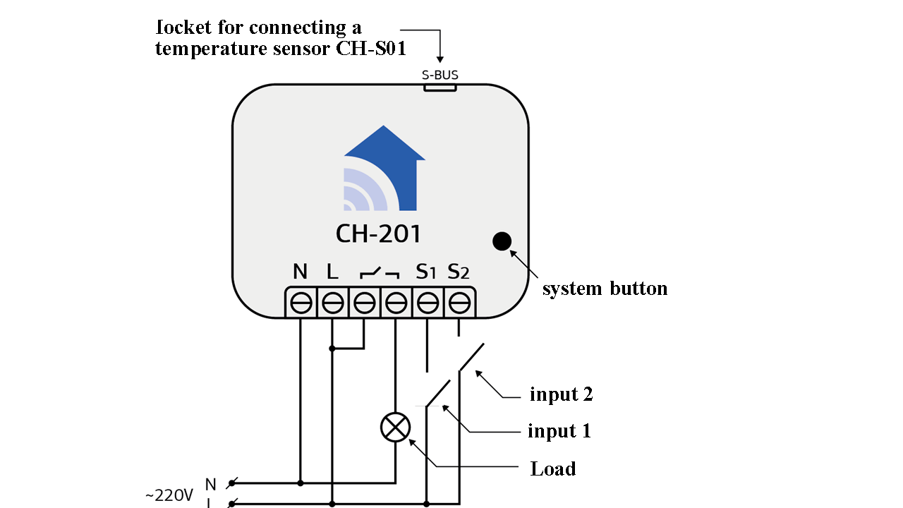
220V load connection diagram (Fig.2)
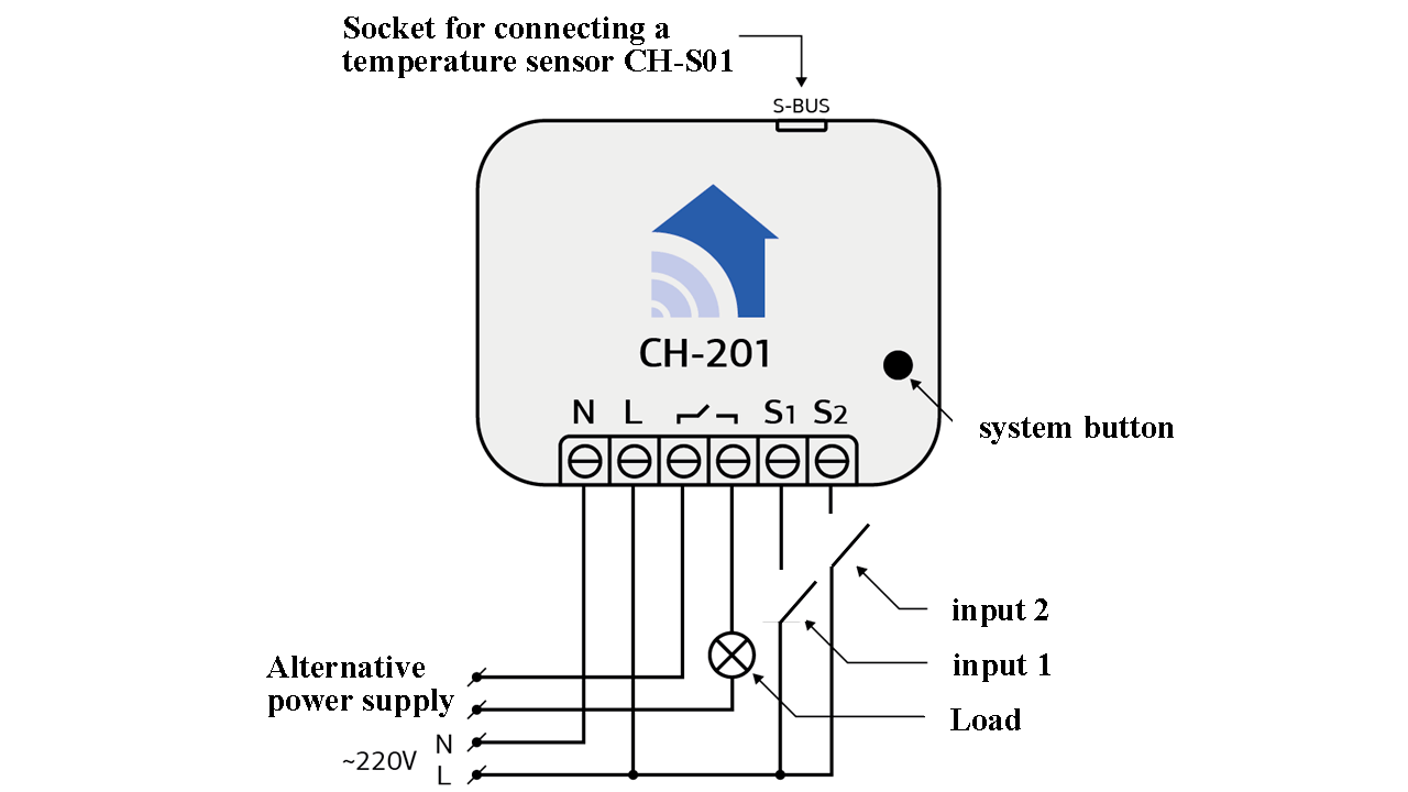
Load connection diagram with alternative power supply (Fig.3).
The diagram shows:
-
- L -phase;
- N -is the neutral wire;
- _/_ - normally open relay;
- S1 -Contact for Input 1 ;
- S2 -contact for Input 2 .
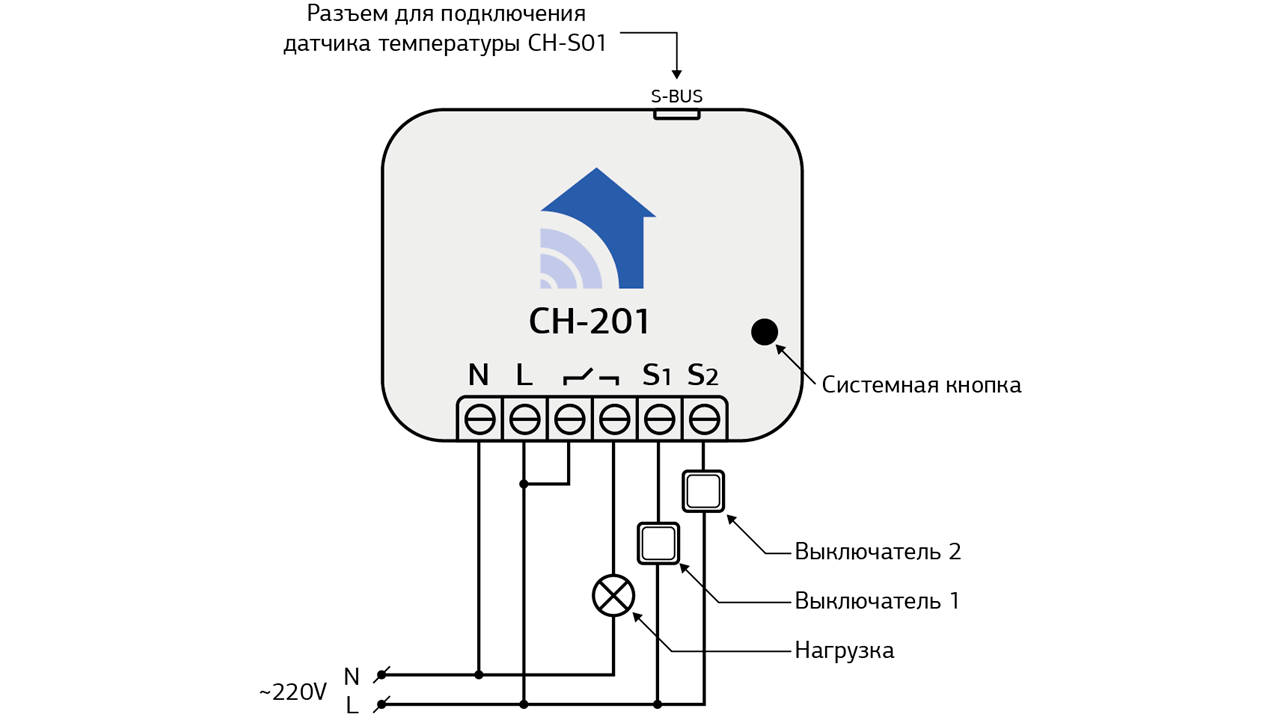
220V load connection diagram (Fig.2)
Load connection diagram with alternative power supply (Fig.3).
The diagram shows:
-
- L - phase;
- N ¬ neutral wire;
- _/_¬normally open relay;
- S1 contact for Switch 1 - thermostat (On/Off);
- S2 ¬ Contact for Switch 2 - Turbo mode (On/Off).
Parameters
For your convenience, you can fine tune the unit using a number of configuration parameters. To change the thermostat parameters, select the corresponding device parameter number (see controller manual), change the corresponding value and save the settings.
- 0. Close the relay when the thermostat is in "heating" mode and open when the set temperature is reached (Default). The most commonly used mode, used when the heater is connected directly through a thermostat or normally closed valves.
- 1. Open the relay when the thermostat is in "heating" mode and close it when the set temperature is reached. Can be used with a limited list of special equipment (normally open valves, etc.).
It is not possible to always maintain one exact temperature value due to inertia. In this case, two values are used to maintain the temperature mode: minimum and maximum. When reaching the minimum value - heating will be turned on, when heating to the maximum value - the heating element will be turned off. For user convenience, the controller assumes temperature regulation with only one value, from which the thermostat will calculate the previously mentioned "minimum" and "maximum" values of the temperature range. We recommend using a small range of 1 degree for greater comfort and the most accurate match to the selected temperature. If your heating element consumes a significant amount of energy when turned on, then we recommend reducing the number of on-off cycles by increasing this parameter. With our thermostat you can always achieve the optimum operating mode by experimentation or by asking our specialists for help.Allowable value from 1 to 7 degrees:
— 1 degree (Default).
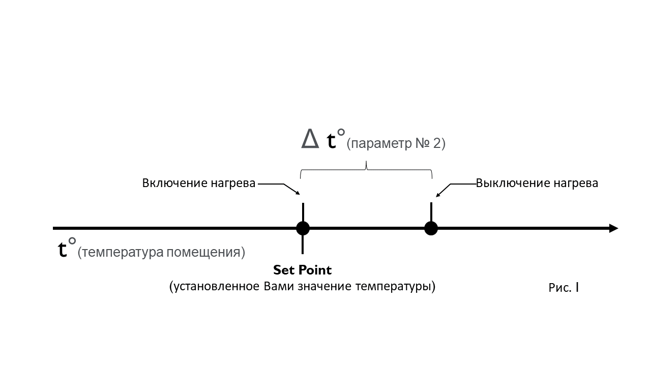
0 Switching on heating mode at room temperature, switching off at room temperature + Δt (Fig. 1);
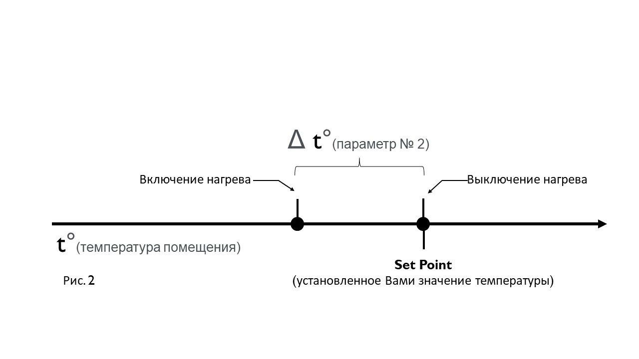
1 Switching on the heating mode at room temperature - Δt, switching off at room temperature (Fig. 2);
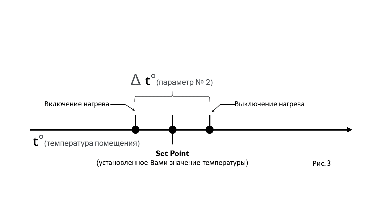
2 Switching on the heating mode at room temperature - ½ Δt, switching off at room temperature - ½ Δt (Default) (Fig.3).
This parameter sets the thermostat operation mode if the thermostat has not received data from the original temperature sensor within 30 seconds or from a remote temperature sensor within the set time (parameter #7)
0 The thermostat is off (recommended for electric underfloor heating);
1 Thermostat is on
2. Periodic On/Off (Default).
This parameter specifies for how long the thermostat will be active when operating in alarm mode. The unit of measure is seconds. Provided the parameter 4 is set to on/off.
Allowable value (10-30000 sec):
30 seconds (Default).
This parameter specifies for how long the thermostat will be inactive when operating in alarm mode. The unit of measure is seconds. Provided the parameter 4 is set to on/off.
Allowable value (10-30000 sec):
30 seconds (Default).
After the specified time has elapsed, the absence of data from the room sensor will be considered a failure.
If the temperature sensor fails, the thermostat will go into alarm mode. In this mode, the temperature will be set to 0°C, the thermostat will go to the state defined in Parameter 4, and an alarm will be sent to the first group of links. The response of the controller will depend on the controller settings. Refer to your controller's user manual for more information.
Allowable value (100-30000 sec):
30000 seconds (Default).
The user-set temperature cannot be set lower than the permissible value (-127°C to 127°C)*:
4 degrees (Default).
The temperature set by the user may not be higher than this value, including when using the turbo mode (e.g. the temperature of the underfloor heating with a wooden base may not be higher than 27°C). Permissible value from -127 to 127°C;
30 degrees (Default).
Temperature sensor operating parameters
The CH-201 thermostat can be equipped with the CH-S01 high-precision temperature sensor. If it is more convenient to use a remote temperature sensor in your network configuration, you need to change this parameter.
A remote temperature sensor is any temperature sensor in your network. It can be a stand-alone device such as the CH-STH, or it can be part of another device (for example: a temperature sensor connected to the CH-101 module).
Operation modes of the remote sensor:
- the thermostat can query the temperature at a room sensor (if data is requested, the room sensor must be added to the 2nd group of links of the thermostat). For the device to work correctly, you only need to have one temperature sensor in the link group. Note that some controllers, after connecting a new device to the network, spontaneously add themselves to all groups of links. In this case, you will need to remove the controller from the second group of links and add the appropriate temperature sensor to it.
- the thermostat can expect - temperature data from the room sensor. To do this you need to add the thermostat to the corresponding link group of the room sensor where the temperature data comes (see the sensor manual). For example, when using a temperature sensor connected to the CH-101 module, add the thermostat to the 4th or 5th link group and select value 7 (send actual sensor value to another device) in Parameter #24 or #29 (depending on the sensor serial number).
Consider the fact that the thermostat will go into alarm mode until it receives temperature readings.
0 The built-in temperature sensor (Default);
1 Polling the room temperature sensor;
2 Waiting for data from the room temperature sensor.
When selecting a value, take into account the fact that too frequent polling of the sensor can overload the network
The allowable value is from 15 - 6000 seconds:
300 seconds (Default).
The thermostat can send data to the controller and/or other devices on the network when the temperature changes by a specified value. Set this parameter based on your network configuration to avoid overloading.
The permissible value is from 1 to 16 degrees:
1 degree (Default).
The thermostat can send data at certain intervals, e.g. every 2 minutes. The value starts counting down from the last successful sending of data.
The allowable value is from 10 to 600 seconds:
300 seconds (Default).
In some temperature sensor locations, the measured values need to be corrected.
0. (Default) Send the actual temperature (hereinafter t);
1. t +1°С;
2. t +2°С;
3. t +3°С;
4. t +4°С;
5. t +5°С;
6. t -1°С;
7. t -2°С;
8. t -3°С;
9. t -4°С;
10. t -5°С.
The CH-201 thermostat can be equipped with the CH-S01 high-precision temperature sensor. In this parameter you can choose whether to display this sensor as a separate widget (endpoint) or not.
0. Do not show(Default);
1. Showing
This thermostat supports cooling mode and heating mode. It can also operate in both modes.
0. The thermostat only supports the heating mode (Default);
1. The thermostat only supports cooling mode
For V.3 devices
- 0. Close the relay when the thermostat is in "heating" mode and open when the set temperature is reached (Default). The most commonly used mode, used when the heater is connected directly through a thermostat or normally closed valves.
- 1. Open the relay when the thermostat is in "heating" mode and close it when the set temperature is reached. Can be used with a limited list of special equipment (normally open valves, etc.).
It is not possible to always maintain one exact temperature value due to inertia. In this case, two values are used to maintain the temperature mode: minimum and maximum. When reaching the minimum value - heating will be turned on, when heating to the maximum value - the heating element will be turned off. For user convenience, the controller assumes temperature regulation with only one value, from which the thermostat will calculate the previously mentioned "minimum" and "maximum" values of the temperature range. We recommend using a small range of 1 degree for greater comfort and the most accurate match to the selected temperature. If your heating element consumes a significant amount of energy when turned on, then we recommend reducing the number of on-off cycles by increasing this parameter. With our thermostat you can always achieve the optimum operating mode by experimentation or by asking our specialists for help.Allowable value from 1 to 7 degrees:
— 1 degree (Default).
0 Activation of heating mode at room temperature, deactivation at room temperature + Δt;.
1 Heating mode switches on at room temperature - Δt, switching off at room temperature;
2 Switching on the heating mode at room temperature - ½ Δt, switching off at room temperature - ½ Δt (Default)(Fig.1).
.png)
THIS PARAMETER SETS THE OPERATING MODE OF THE THERMOSTAT IF THE THERMOSTAT HAS NOT RECEIVED DATA FROM THE NORMAL TEMPERATURE SENSOR WITHIN 30 SECONDS, OR FROM THE ROOM TEMPERATURE SENSOR WITHIN THE SET TIME (PARAMETER NO. 5).
If you use a thermostat to control the electric underfloor heating element, set this parameter to 0. This will prevent overheating and possible failure of the heating element if there is no data from the temperature sensor.
0 The thermostat is off (recommended for electric underfloor heating);
1 The thermostat is on (Default).
After the specified time has elapsed, the absence of data from the room sensor will be considered a failure.
If the temperature sensor fails, the thermostat will go into alarm mode. In this mode, the temperature will be set to 0°C, the thermostat will go to the state defined in Parameter 4, and an alarm will be sent to the first group of links. The response of the controller will depend on the controller settings. Refer to your controller's user manual for more information.
Allowable value (100-30000 sec):
30000 seconds (Default).
The user-set temperature cannot be set lower than the permissible value (-127°C to 127°C)*:
4 degrees (Default).
The temperature set by the user cannot be higher than this value, including when using the turbo mode (e.g. the temperature of the underfloor heating with a wooden base cannot be higher than 27°C). Permissible value from -127 to 127°C.Permissible value (-127 to 127°C)*;
30 degrees (Default).
Turbo mode is used to dry floors after wet cleaning. Turbo mode will maintain the maximum temperature for a set period of time, after which the thermostat will switch to the previously set by the user operating mode.
Allowable value (from 100 to 1200 seconds):
120 seconds (default).
This parameter determines whether the turbo mode is activated when the thermostat is off.
0 Enable (Default).
1 Do not include. (Default).
Temperature sensor operating parameters
The CH-201 thermostat can be equipped with the CH-S01 precision temperature sensor. If it is more convenient to use a remote temperature sensor in your network configuration, you need to change this parameter.
A remote temperature sensor is any temperature sensor in your network. It can be a stand-alone device such as the CH-STH, or it can be part of another device (for example: a temperature sensor connected to the CH-101 module).
Operation modes of the remote sensor:
- the thermostat can query the temperature at a room sensor (if data is requested, the room sensor must be added to the 2nd group of links of the thermostat). For the device to work correctly, you only need to have one temperature sensor in the link group. Note that some controllers, after connecting a new device to the network, spontaneously add themselves to all groups of links. In this case, you will need to remove the controller from the second group of links and add the appropriate temperature sensor to it.
- the thermostat can expect - temperature data from the room sensor. To do this you need to add the thermostat to the corresponding link group of the room sensor where the temperature data comes (see the sensor manual). For example, when using a temperature sensor connected to the CH-101 module, add the thermostat to the 4th or 5th link group and select value 7 (send actual sensor value to another device) in Parameter #24 or #29 (depending on the sensor serial number).
Consider the fact that the thermostat will go into alarm mode until it receives temperature readings.
0 The built-in temperature sensor (Default);
1 Polling the room temperature sensor;
2 Waiting for data from the room temperature sensor.
When selecting a value, take into account the fact that too frequent polling of the sensor can overload the network
The permissible value is from 15 - 600 seconds:
300 seconds (Default).
The thermostat can send data to the controller and/or other devices on the network when the temperature changes by a specified value. Set this parameter based on your network configuration to avoid overloading.
The permissible value is from 1 to 16 degrees:
1 degree (Default).
The thermostat can send data at certain intervals, e.g. every 2 minutes. The value starts counting down from the last successful sending of data.
The allowable value is from 10 to 600 seconds:
300 seconds (Default).
In some temperature sensor locations, the measured values need to be corrected.
0. (Default) Send the actual temperature (hereinafter t);
1. t +1°С;
2. t +2°С;
3. t +3°С;
4. t +4°С;
5. t +5°С;
6. t -1°С;
7. t -2°С;
8. t -3°С;
9. t -4°С;
10. t -5°С.
The CH-201 thermostat can be equipped with the CH-S01 high-precision temperature sensor. In this parameter you can choose whether to display this sensor as a separate widget (endpoint) or not.
0. Do not show(Default);
1. Showing
This thermostat supports cooling mode and heating mode. It can also operate in both modes.
0. The thermostat only supports the heating mode (Default);
1. The thermostat only supports cooling mode
2.The thermostat supports both modes
Related
Devices can communicate with each other as well as exchange data and other information both with the central controller and directly without the controller. Each event can have its own list of recipients, called a group of links. Refer to your controller's user manual to set up the links. The CH-201 thermostat has a group of links for adding an external temperature sensor, as well as a main group of links for communicating with the controller.
-
-
- Group 1 - A group of devices that receive temperature reports and alarms in case the sensor is disconnected. There can be up to 10 devices in this group, taking into account the controller that is recommended to be included in this group.
- Group 2 — Группа связей для подключения удалённого датчика температуры. При добавлении в эту группу датчик температуры , термостат будет query temperature at the sensor. Only one temperature sensor can be added to this group.
-
Attention! Note that not all devices can respond to such requests. The CH-STH temperature sensor is a battery-operated device, so it is in sleep mode most of the time to save power and does not respond to requests. In this case it can send the temperature data to the thermostat itself.
Manufacturer's warranty.
The warranty period is 1 year from the date of sale. Products that were transported, stored, assembled and operated with violations of the requirements for these products, as well as having mechanical damage - warranty replacement is not subject to the warranty.
Do not use the unit in any way other than that specified in this manual. The manufacturer shall not be liable for any warranty in case of improper use, modification or painting of the device. Immediately after opening the package, be sure to check the device for damage. If there is visible damage, do not connect or use the device.
Briefly about the C-Home system
All C-Home devices use a reliable and completely safe radio channel, on the basis of which the modules are combined with each other in a single network, which allows you to receive and transmit control signals to other devices in the network, using intermediate neighboring nodes.
The C-Home system has the ability to automatically reconstruct data transmission routes, depending on external factors, for example, if there is an obstacle between two neighboring devices, the signal will go through other nodes in the network in range.
C-Home is a two-way network. The devices can not only send control commands, but also wait for confirmation of their delivery and query the current status of the device. If the sending was not successful, the system tries to send the command another way.
The central element of the C-Home network is the Butler, which stores information about the network topology. It allows you to add and remove devices from the network and control all devices remotely. Not only C-Home company devices, but also more than 4,500 devices of various types and manufacturers can be connected to the Butler, which enables the implementation of any home automation tasks.